Command description:
Polygons, routes and placemarks can be imported from Google Earth to AutoCAD. Polygons can be imported as 2D or 3D polylines projected to terrain, optionally applying fill color. Placemarks can be imported as blocks with elevation, including placemark name and description. A Symbol Library is included where you can select the placemark block to be inserted, or you can add your own blocks.
Dialog box settings (Objects tab):
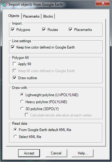
Import objects from Google Earth (Objects tab)
ØImport:
·Polygons. Imported polygons from Google Earth to AutoCAD will be drawn as closed polylines.
·Routes. Imported routes from Google Earth to AutoCAD will be drawn as open polylines.
·Placemarks. Imported placemarks from Google Earth to AutoCAD will be drawn as points and block inserts.
ØLine settings
·Keep line color defined in Google Earth. If you deselect this option objects will be imported to AutoCAD and will be drawn using the current color.
ØPolygon fill:
·Apply fill. A solid hatch will be applied to polygons when imported to AutoCAD.
·Keep color defined in Google Earth. If you deselect this option a solid hatch using the current color will be applied to polygons when imported, otherwise the fill color they had in Google Earth will be used.
·Draw outline. If hatching will be applied to the imported polygons, you can choose not to draw their outline.
ØDraw with:
·Lightweight polyline. Imported polygons and routes will be drawn with regular polylines in AutoCAD.
·Heavy polyline. Imported polygons and routes will be drawn with heavy polylines in AutoCAD.
·3D polyline. Imported polygons and routes will be drawn with 3D polylines in AutoCAD, which can have different Z elevations in each vertex.
·Draw vertices with Z elevations. Elevation in each vertex will be calculated to draw imported objects with 3D polylines.
ØRead data.
·From Google Earth default KML file. Data will be read from the 'myplaces.kml' Google Earth file.
·Select KML file. Data will be read from a KML file selected by the user.
Dialog box settings (Placemarks tab):

Import objects from Google Earth (Placemarks tab)
ØElevation:
·Projected to terrain. Elevation will be calculated to be on the ground in the placemark's XY position.
·Placemark elevation. Elevation will be the same as the placemark elevation in Google Earth.
·Zero. Elevation will be at sea level (absolute zero)
ØAnnotations:
·Text size. Set placemark's name and description text size in drawing units.
·Text color. Select color for placemark's name and description text.
·Text layer. Select layer for placemark's name and description text.
·Text style. Select text style for placemark's name and description.
·Annotate name. Select to write placemark's name in the drawing.
·Annotate description. Select to write placemark's description in the drawing.
Dialog box settings (Blocks tab):
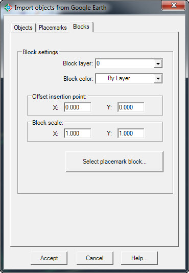
Import objects from Google Earth (Blocks tab)
ØBlock settings.
·Block layer. Select layer for placemark's block insert when imported to AutoCAD.
·Block color. Select color for placemark's block insert when imported to AutoCAD.
·Offset insertion point. Set displacement of placemark's position in horizontal (X) and vertical (Y) direction in the selected units (meters or feet).
·Block scale. Set scale applied to the placemark's block insert.
·Select placemark block. A dialog box will appear to select the block reference that will be inserted in the placemark's position.
.png)
Placemark block library
Tips:
·Before using this command the current drawing must be georeferenced to establish the conversion parameters between the drawing and the latitude/longitude coordinates of the corresponding site.
·You can add custom placemark block inserts using the CAD-Earth's command to make point blocks. A block insert icon will appear in the 'Select placemark block' dialog box the next time you import placemarks from Google Earth.
·Imported polygon polylines can be used to import the corresponding image or terrain configuration to AutoCAD by using the CAD-Earth commands to import a terrain mesh or image from Google Earth.
·If you intend to share Google Earth information you can save to a KML file. This file can be opened by other Google Earth users so they can see your information.
·If you add a polygon, route or placemark in Google Earth you must save the information to the default KML file selecting File > Save > Save My Places so CAD-Earth can read the information from the default Google Earth KML file. Objects must be added to 'My places' folder. You can also close Google Earth and save the changes.
·Google Earth can be closed when importing objects. CAD-Earth reads information from the default KML file (myplaces.kml) or from a KML file supplied by the user to import objects to AutoCAD.
Related topics:
·How to save Google Earth information to a KML file (video).
·How to save information in Google Earth's 'My Places' folder (video)
·Import image from Google Earth
·Import terrain mesh from Google Earth
Copyright © 2014 Arqcom Software
Google Earth© is a registered trademark of Google inc. All other trademarks are the property of their respective owners.